
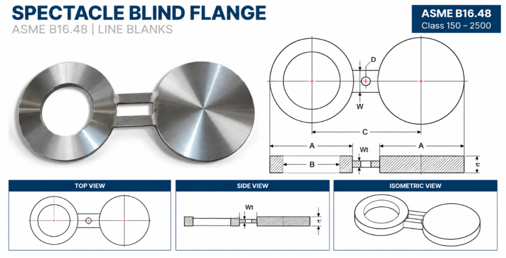
ASME B16.48 | Spectacle / Figure-8 Blinds | Line Blanks | Class 150–2500
Elite provides Spectacle Blinds, also known as Figure-8 Blinds, for positive mechanical isolation in industrial piping systems. A Spectacle Blind combines a solid blind section and an open spacer section connected by a central web, allowing the line to be changed between the isolated and open positions by rotating the assembly.
These line blanks are commonly used in piping maintenance, shutdowns, turnarounds, pressure testing and process isolation applications where a clearly visible mechanical isolation point is required.
| Specification | Details |
|---|---|
| Product Type | Spectacle Blind / Figure-8 Blind / Spectacle Line Blank |
| Primary Standard | ASME B16.48 – Line Blanks |
| Size Range | NPS 1/2–24; larger sizes available to project requirements |
| Pressure Classes | 150, 300, 600, 900, 1500, 2500 |
| Configuration | Blind + Spacer / Figure-8 |
| Installation | Between mating pipe flanges |
| Operating Positions | Open Position / Isolated Position |
| Construction | Plate, forged or machined construction, as applicable |
| Thickness | ASME B16.48 or project specified |
| Flange Compatibility | Based on applicable mating flange dimensions |
| Identification | Integral web / handle for visual identification |
| Surface Finish | Standard or customer specified |
| Heat Treatment | As required by material specification |
| Marking | Size, class, material, heat number and required identification |
| Inspection | Visual, dimensional, chemical and mechanical testing as applicable |
| NDE | PMI, UT, MT, PT and other methods as specified |
| Documentation | MTC, EN 10204 3.1/3.2, COC and inspection reports |
| Custom Requirement | Details |
|---|---|
| Nominal Size | NPS or custom diameter |
| Pressure Class | 150–2500 or project specified |
| Material | Required material grade |
| Blind Thickness | Standard or project specified |
| Spacer Bore | Required pipe / flow diameter |
| Outside Diameter | As required |
| Web Dimensions | Project specified |
| Bolt Pattern | Based on mating flange |
| Flange Compatibility | Project specified |
| Facing Arrangement | According to mating flange / project requirements |
| Marking | Customer requirements |
| NDE | Project specified |
| Inspection | ITP / third-party requirements |
| Inspection / Documentation | Availability |
|---|---|
| Material Test Certificate | Available |
| EN 10204 3.1 | Available |
| EN 10204 3.2 | Where specified |
| Certificate of Conformance | Available |
| Dimensional Inspection | Available |
| Chemical Analysis | Material dependent |
| Mechanical Testing | Material dependent |
| Heat Treatment Records | Where applicable |
| PMI | As specified |
| Ultrasonic Testing (UT) | As specified |
| Magnetic Particle Testing (MT) | As specified |
| Liquid Penetrant Testing (PT) | As specified |
| Visual Inspection | Standard |
| Third-Party Inspection | Available |
| ITP | Project specific |
| Material Traceability | Maintained |
| Packing & Marking Records | Available |
For large-diameter or pipeline applications, associated flange and piping dimensions may be governed by ASME B16.47, MSS SP-44 or other project-specified standards, as applicable.
Important: Spectacle Blinds / Figure-8 Blinds are line blanks rather than conventional pipe flanges. ASME B16.48 is therefore the primary dimensional standard.
Carbon Steel
ASTM A105/A105N, ASTM A181, ASTM A350 LF2/LF3 and ASTM A694 F42, F46, F52, F60 and F65.
Stainless Steel
ASTM A182 F304/F304L, F316/F316L, F321/F321H, F347/F347H, F310/F310S, F317 and F904L.
Duplex & Super Duplex
ASTM A182 F51, F53 and F55.
Alloy Steel
ASTM A182 F1, F5, F9, F11, F12, F22, F91 and F92.
Nickel Alloys
Nickel 200/201, Monel 400/K500, Inconel 600/601/625/800/825, Hastelloy C276 and Alloy 20.
Copper-Nickel Alloys
UNS C70600 and C71500, including 90/10 and 70/30 Cu-Ni alloys.
Material selection is based on operating pressure, temperature, process fluid, corrosion conditions, mechanical requirements and applicable project specifications.
Closed / Isolated Position
The solid blind portion is positioned between the mating flanges to completely block the flow path and provide positive mechanical isolation.
Open Position
The spacer portion is positioned between the flanges, allowing the piping system to remain open for normal operation.
Figure-8 Construction
The blind and spacer are permanently connected by a central web. This allows the operating position to be identified visually without removing the line blank from the piping system.
Elite’s manufacturing and inspection process can include:
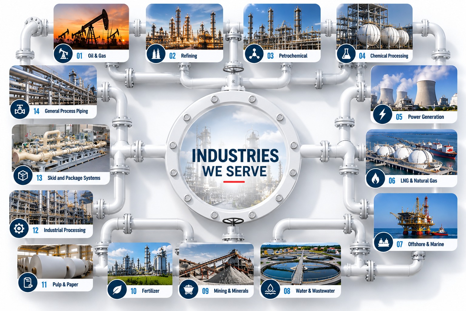
Spectacle Blinds are commonly used for positive isolation and line management in:
For quotation, provide:
Size + Pressure Class + Spectacle Blind Type + Material + Thickness + Flange Configuration + Quantity + Inspection Requirements
Example
6″ Class 600 Spectacle Blind / Figure-8 Blind, ASME B16.48, ASTM A105N, suitable for applicable RF flange assembly, EN 10204 3.1.


